In this tutorial,we suppose that GMF is already installed into Eclipse. We will copy and use the ecore metamodel fsm.ecore stored into fr.irisa.triskell.samples.fsm.demoAspect/metamodels/ after creating a new general project. The solution of this tutorial is available clicking on File -> New -> Example -> Kermeta Samples -> FSM Solutions. So, you can retrieve the following plugins :
fr.irisa.triskell.kermeta.samples.fsm.gmf
fr.irisa.triskell.kermeta.samples.fsm.gmf.edit
fr.irisa.triskell.kermeta.samples.fsm.gmf.editor
fr.irisa.triskell.kermeta.samples.fsm.gmf.diagram
fr.irisa.triskell.kermeta.samples.fsm.gmf.tests
Even if these plugins do not have the same name as the plugins you will created it is the same diagram editor .
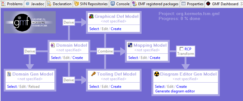
GMF uses six files to create a generated graphical editor for instances of a given metamode like shown in the following DashBoard ( all the steps are finished). For more information about DashBoard View please refer to the section Create a new GMF project.
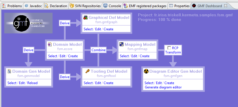
As you can see, the generation of a GMF graphical editor contains six steps :
Domain model : the metamodel we want to use to create the graphical editor. For this metamodel, you have the choice between several kinds of metamodels : Annotated Java code , Ecore model, Rose class model, UML model or XML Schema). In this tutorial we will use the ecore metamodel of FSM.
Domain Gen Model (.genmodel) : this file is used to generate the domain model code with EMF (it is the EMF file genModel)
Graphical Def Model (.gmfgraph) : this file is used to define the graphical elements for your domain model
Tooling Def Model (.gmftool) : this file is used to define the palette of tools that you can use in the graphical editor
Mapping Model (.gmfmap) : this file links the domain model, the graphical model (.gmfgraph) and the tooling model (.gmftool)
Diagram Editor Gen Model (.gmfgen) : this final file us used to generate the GMF graphical editor in addition to the EMF code generated by the .genmodel file
![[Tip]](gfx/admonitions/tip.gif) | Tip |
|---|---|
You can generate two kind of graphical editor with GMF : a plugin graphical editor integrated with Eclipse or as an RCP (Rich Client Platform) application which consists in an autonomous application. To generate a RCP application, just click into RCP on the DashBoard. In this tutorial we will create a GMF editor as an Eclipse plugin. |
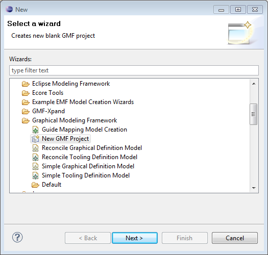
To start with, click on File-> New->Other-> Graphical Modeling Framework -> New GMF Project.
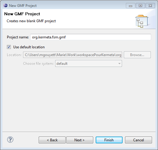
Then, you can give to it the name org.kermeta.fsm.gmf like shown below.
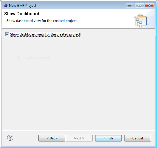
Select the DashBoard view, it will be useful to use GMF. This dashboard resumes
all the necessary steps to create an editor with GMF and you can navigate between these
steps with it.
| Tip |
|---|---|
You can also add this view by selecting the org.kermeta.fsm.gmf in the Package Explorer View and then click on Window->Show view-> Other-> General -> GMF DashBoard. |
At the beginning, the DashBoard looks like this :
Now, we will follow all the steps presented into the last section.
This section details more all the steps. To start with, copy the file fsm.ecore stored into fr.irisa.triskell.kermeta.samples.fsm.demoAspects/metamodels/fsm.ecore into org.kermeta.fsm.gmf/model. In all this section we use the Dashboard view.
On the DashBoard view, in the case Domain model click on Select and choose the fsm.ecore from org.kermeta.fsm.gmf. Then, click on the Derive at the left to create the EMF GenModel.
The following wizard appears to choose the name of the .genmodel file. (You can make appears it clicking on Select in the Domain Gen Model Case).
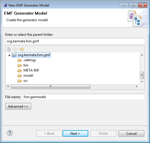
Click on Next. In the following wizard select ecore model.
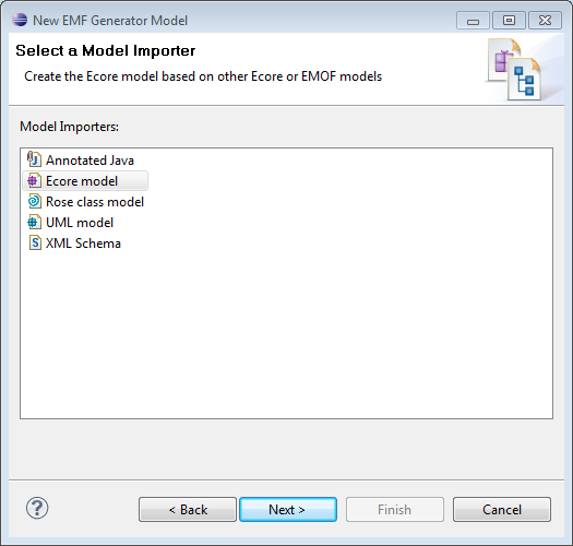
Click on Next. For the next wizard do not forget to click on load.
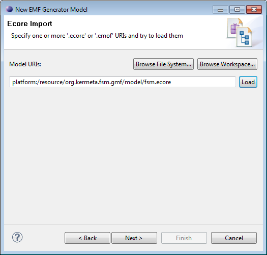
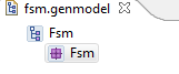
Then click on Next and Finish. The file fsmStatic.genmodel appears on the
project and the DashBoard. Open it and click on the arrow near Fsm. Right click on Fsm ->
Generate All. It generates the EMF Java code for the domain model.
For the next steps you can choose between begin with Graphical Def Model or Tooling Def Model. We start with Graphical Def Model.
Click in Derive at the top of the Domain Model case. Like for GenModel you can select the name. Then, select the root metaclass of your metamodel, in your case FSM.
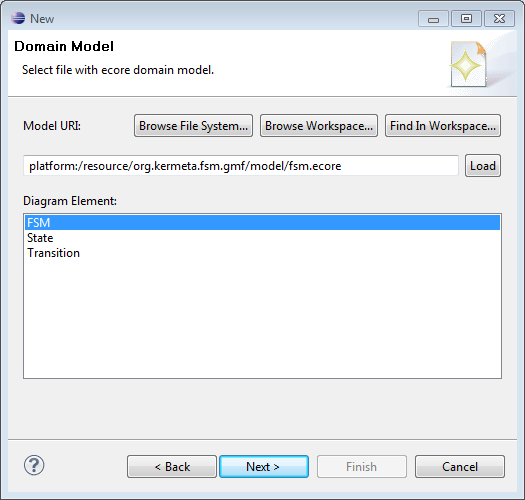
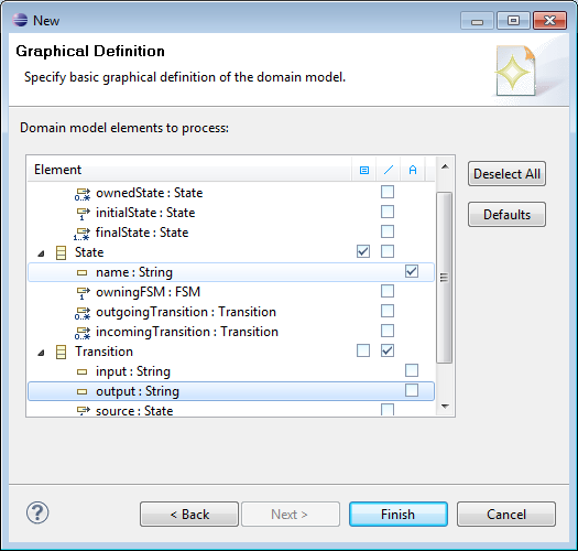
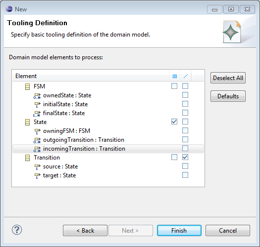
In this tutorial we want simply to create a graphical editor for States with
their name and Transition. Select the elements like in the following figure :
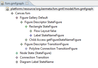
The resulted file fsm.gmfgraph looks like this :
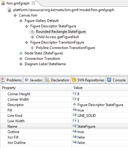
Now, we want to do changes on fsm.gmfgraph file. To start with we want to
replace the state rectangle by a rounded state rectangle. Start with suppress the
Rectangle State figure ( Right click on it -> Delete). Click on FigureDescriptor
StateFigure -> New Child -> Rounded Rectangle. Then click on the created Rectangle and use
the Properties view to edit its name as StateFigure.
| Tip |
|---|---|
If you do not see the Properties View go to Window-> Show View -> General -> Properties. |
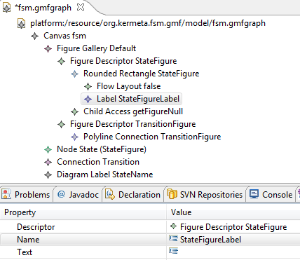
Then right click on Rounded Rectangle StateFigure and choose Flow Layout. Then
right click again and choose Label. Add its name StateFigureLabel in the Properties View.
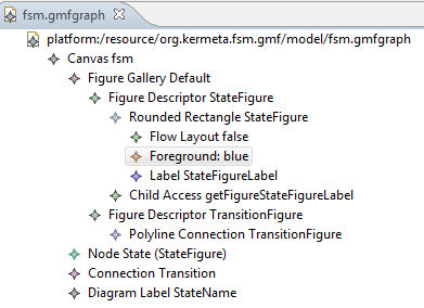
A Diagram Label StateName appears on the gmfgraph file. Now, Click on the Child
Access of the Rounded Rectangle and set its figure property to Label StateFigureLabel.
Then right click on Child Access and choose Refresh. You can add a foreground on your
Rounded Rectangle. For this right click on Rounded Rectangle StateFigure -> Foreground
Color Constant Color and edit the value to blue. The file fsm.gmfgraph should look like
this :
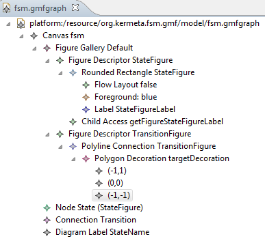
Then we want to customize the connection and add an open arrow on its end. Start with adding a PolylineDecoration (right click on PolylineConnection TransitionFigure -> New Child -> Polyline Decoration). Name it targetDecoration. We need to add three Template Point to draw the arrow. Right click on Polyline Target targetDecoration -> New Child -> Template Point (at the bottom of the contextual menu , use the arrow at the bottom to see all this menu) to add one of them. Then edit them respectively to (-1,1), (0,0) and (-1,-1). Now edit Polyline Connection TransitionFigure and set targetDecoration with Polyline Decoration targetDecoration. The file fsm.gmfgraph should look like this :
Now, we create the tooling model.
Click on Derive at the bottom of the Domain model case. Like for the graphical model choose the file name and the root metaclass (FSM). In this palette we want only to use State and Transition, so select the elements like in the following figure :
The file fsm.gmftool looks like this :
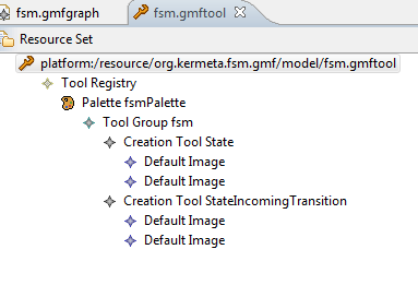
These images can be customized. For more informations please refer to the GMF
documentation.
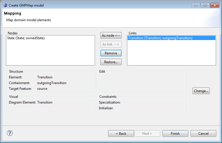
The mapping model (.gmfmap) permits to link .genmodel, .gmfgraph and .gmftool files. In the DashBoard click on Combine. Like for Graphical and Tooling model choose a name and select the root metaclass (FSM). We want to have a very simple editor with simply State and one Transition connector. So, in the last wizard, remove owningFSM and incomingTransition in order to obtain the following wizard:
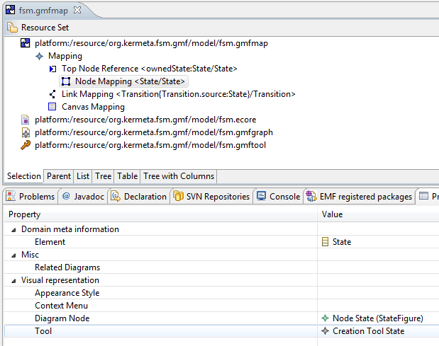
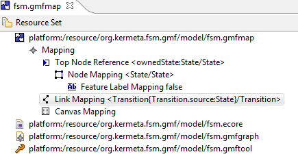
The fsm.gmfmap looks like this
![[Warning]](gfx/admonitions/warning.gif) | Warning |
|---|---|
Do not forget to check if Diagram Node (or Diagram Link) and Tool properties of Node Mapping or Link Mapping have the good values.
|
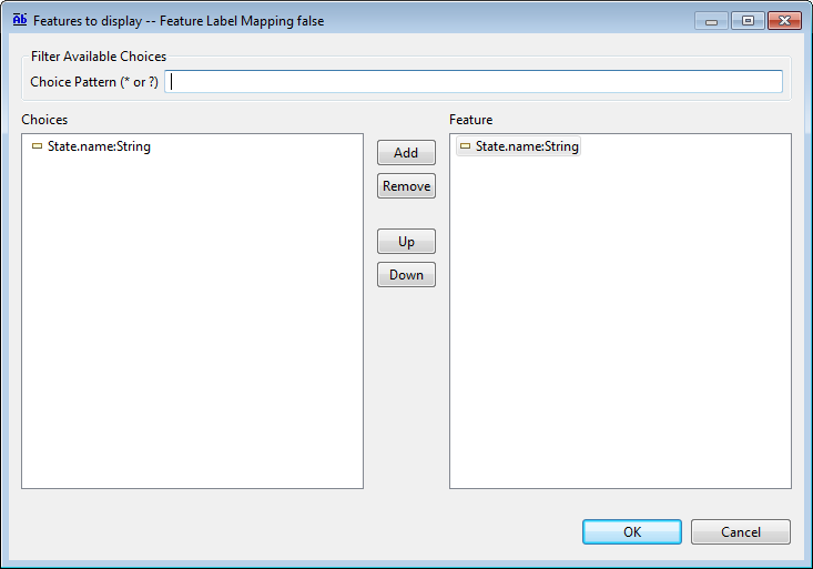
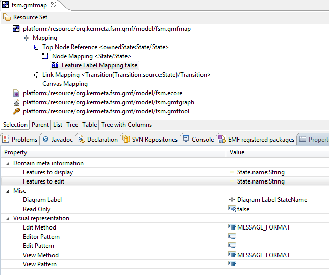
On this file we need to add a Feature Label mapping to manage the name label of the state. Right click on Node mapping State -> New Child -> Feature Label Mapping. Edit the diagram label with Diagram Label StateName. You have also to edit Features to display and Features to edit thanks to the Following wizard :
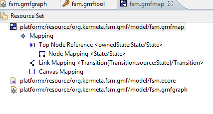
Then, edit the LinkMapping Transition like in the following image :
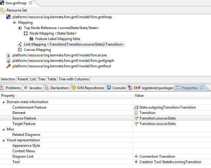
Now, the file fsm.gmfmap looks like this :
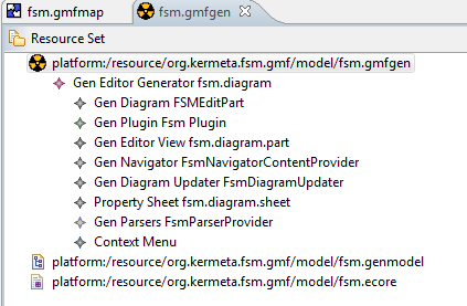
Click on Transform (at the right of the case mapping model) and the file fsm.gmfgen is created. It looks like :
Then click on generate diagram editor. Your project should be like this :
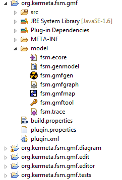
So, we have generated the graphical editor for FSM. The next section explains
how to test it.
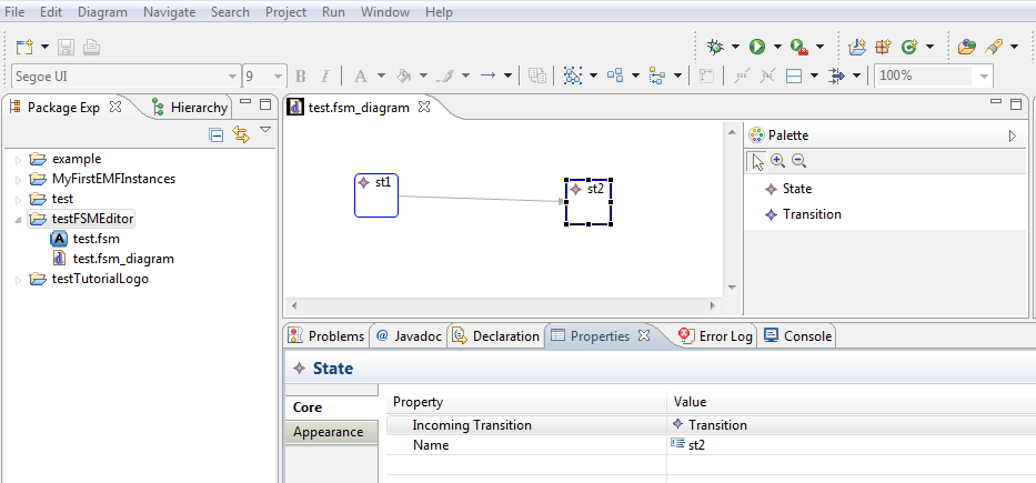
To test the generated editor right click on org.kermeta.fsm.gmf.diagram -> Run as -> Eclipse application. It opens a new Eclipse instance (runtime) where the tested plugin is added. Create a new General Project in this new Eclipse named testFSMEditor. Right click on it -> New -> Example -> Fsm Diagam
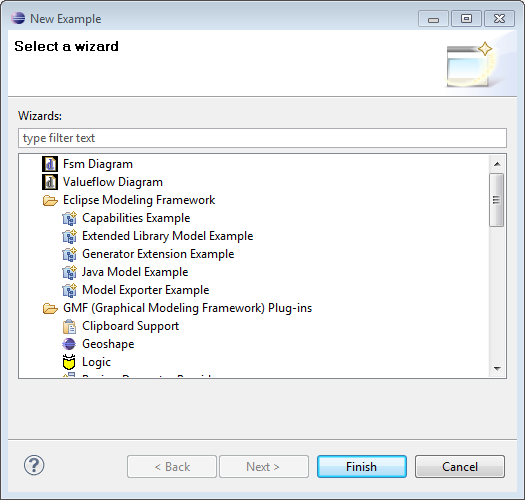
We choose to call our files test.fsm and test.fsm_diagram In this generated editor
the model is stored into two files :
test.fsm : store information on domain model
test.fsm_diagram : store graphical informations
Open the test.fsm_diagram and use the palette. You can have a result like this :
We have created a very little graphical editor to illustrate the FSM example . For more informations please refer to the GMF documentation.